|
Rotator
Brake Delay and Protection Circuit
|
|
|
In 1989 I purchased a new Hy-Gain Tailtwister Rotor to turn my TA-33 beam. I knew of many cases where quick reversal of direction had stripped out the brake in rotators so I decided to design a simple circuit to prevent the problem all together. This circuit has no semiconductor parts outside of the rectifier and some 1N4007 diodes. The relays were purchased at Radio Shack as was the transformer and rectifier. The parts may no longer be available from Radio Shack but are not critical and may be obtained other places. Tony - WA4UPE |
|
| This photo is the underside of the rotor control box with my small control board added. The red arrows point to the two screws which are used to mount the board by way of metal standoffs which you can see in the next photo. The one on the right and the one just to the left of it are also used to mount the 12 VAC transformer. |
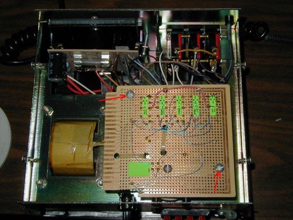 |
| In this photo the board is lifted so you can see the component side. You can also see the metal standoffs which are used to mount the board to the control chassis. |
 |
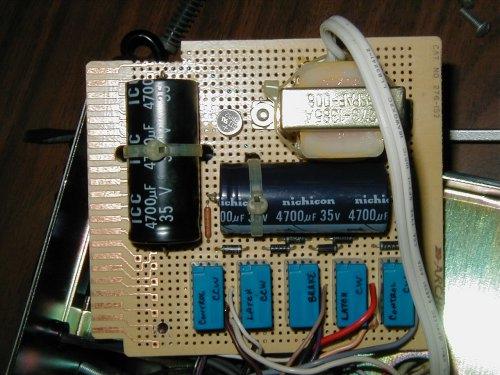
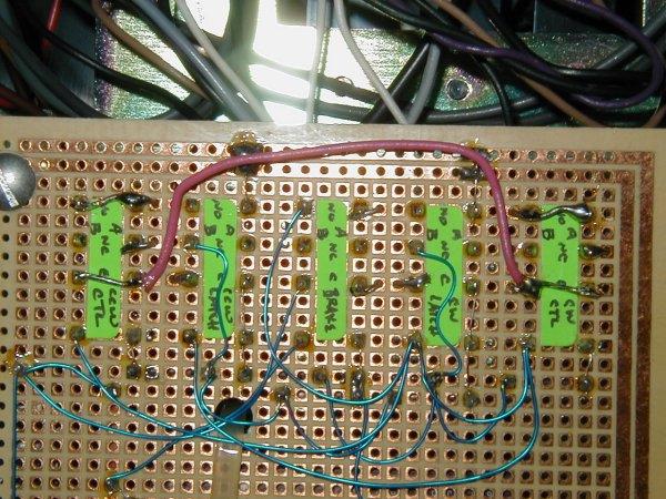
| Component side of the board. you can clearly see the 12 VAC transformer, the small bridge rectifier, the two electrolytic capacitors, the resistor, the diodes and the relays. The AC power for the transformer is connected directly to the transformer with the grey colored zip cord and is connected parallel to the primary of the meter transformer. |
 |
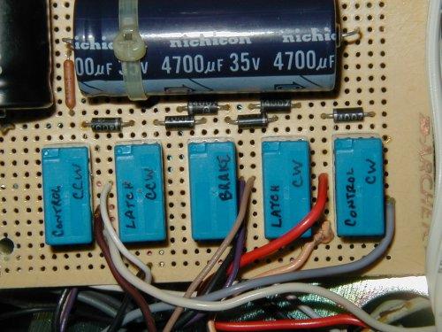
| The relays are shown here with all the connecting wires entering the board from this side and being soldered into pads on the opposite side. |
 |
|
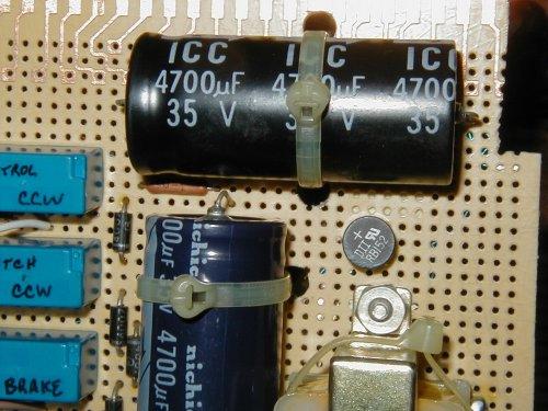
Here you
have detail of the rectifier, resistor and electrolytic capacitors.
Nylon ties are used to hold them down to the board.
|
 |
| The wiring side of the board showing relay connections, point to point wiring using blue wire wrap wire and the tiewraps used to physically attach the electrolytic capacitors. |
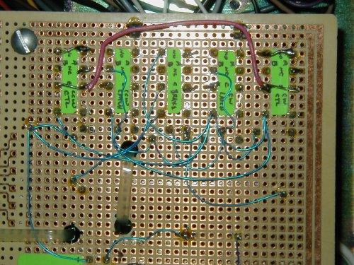 |
| Here's a closeup of the wiring of the relays. The wire connections to the control box come into this board from the component side and can be seen adjacent to the relays. |
 |
| Connecting the circuit to the rotator control: | |
|
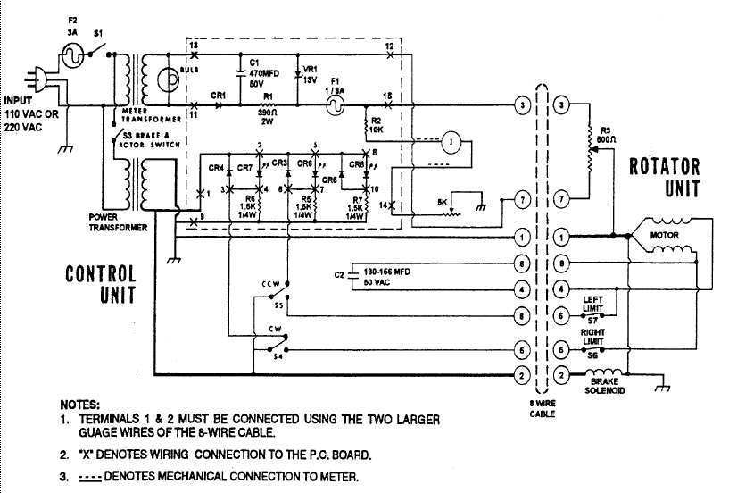
This delay circuit is quite simple to construct and connect to the rotator control box. The circuit is actually performing the job of the BRAKE, CW and CCW switches on the front panel. The front panel CW and CCW switches control this circuit. The front panel brake switch remains operational as original but it is not necessary to use it. The connections to the front panel CW and CCW switches are removed and connected to this circuit as shown. The switches are then connected to this circuit using only the common and normally open connections of the switches. The CW and CCW LEDs and the CW and CCW connections to the terminal strip (CW on #5 and CCW on #6) are made to this board as shown. The brake relay has a pair of contacts that parallel the original brake switch (S3). Power to this board is 120 VAC taken from across the meter transformer primary to the primary of the 12 VAC transformer on this board. It is powered any time the ON/OFF switch is in the ON position. |
|
| Theory of operation: | |
|
In the normal rotator control box it is necessary to hold the brake switch down to release the brake before pressing the CW and CCW switch driving the motor. The problem with the original circuit is that if you continue to hold the brake switch down and reverse the direction of the rotator without waiting for the beam to coast to a stop, you can strip gears in the rotator. If you release the direction and brake switch at the same time the brake can engage in the rotator before the antenna has stopped turning and the inertia of the antenna can strip out the brake inside the rotator. With my circuit you no longer need to mess with the brake switch at all. In addition, the brake will never engage before the antenna has had time (around 4 seconds) to coast to a stop. Furthermore, pressing the opposite direction button will do nothing until the 4 second coast down has occured and then the rotator will reverse direction. Pressing either the CW or CCW buttons will make a circuit engaging the brake relay by way of routing diodes from each switch. Power for the brake relay is through the 10 Ohm resistor. A 4700 uf electrolytic capacitor is in parallel with the brake relay and it along with the second 4700 uf capacitor will keep the relay energized for about 4 seconds after the power is removed from the circuit. The brake relay contacts parallel the brake switch contacts so the brake is powered (disengaged). When the brake relay closes it also makes a circuit that applies power to the other relays. By way of routing diodes the appropriate switch will power a relay which will lock out the opposite switch (direction) until the brake circuit is released. The switch also engages the appropriate directional control relay through another routing diode and the control relay makes the circuit to the motor driving it in the desired direction. When you release a direction switch, the power to the motor will be removed immediately through the control relay and the antenna will coast to a stop. Meanwhile, the brake relay is still engaged and keeps the brake off and also keeps the other direction button locked out. Once the 4 second time has passed the brake relay opens, removes power from the brake, the latch relays and control relays and is now ready to repeat the cycle. Releasing one direction and immediately holding the other direction will not hurt the rotor or the controls. Once the time-out occurs, the rotation will resume in the opposite direction. You can, however, immediately continue the rotation in the SAME direction you were going. |
|
| Parts list: | |
|
1 - 12 VAC transformer All these components were purchased at Radio Shack. You may have to get them other places because of the changing stock at RS. |
|
| Modification Schematic: | |
 (click this picture to open a larger printable version in a new browser window) |
|
| Rotator Control Schematic (T2X): | |
 |
|
|
If you have any comments please contact me directly. 73, Tony - WA4UPE |
|
Page updated August 1, 2008