|
|
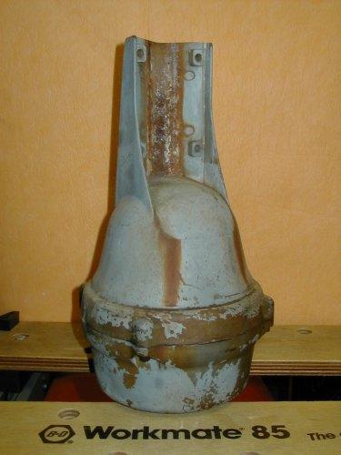
The
rotator before beginning. The outside didn't get a new paint job
this time.
|
|
|
|
|
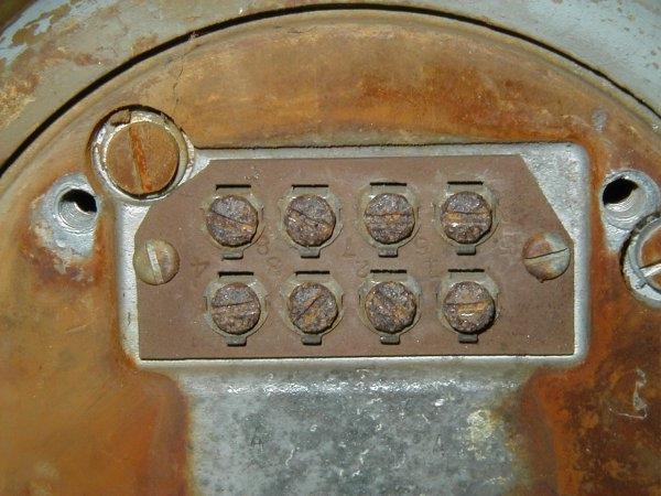
These
rusty screws show you why we need a different connector.
|
|
|
|
|
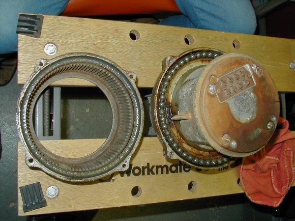
Here
you can see the lower bell housing removed. The BRAKE wedge is
visible sticking out of the body and you can see the slots inside
the lower bell housing that the brake wedge slips into.
|
|
|
|
|
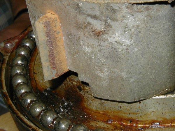
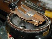
Close-up
of the BRAKE wedge. This was before cleaning so you can see how
bad it was.
|
|
|
|
|
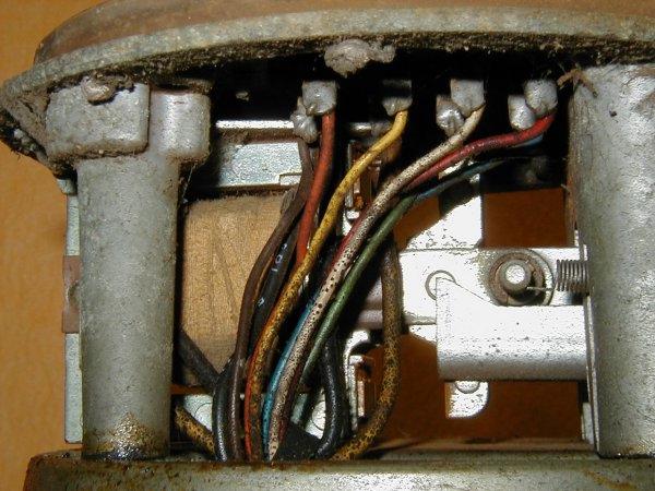
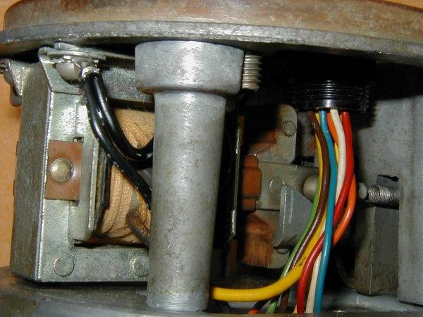
Here
you see the buildup on all the wires and the old connector.
|
|
|
|
|
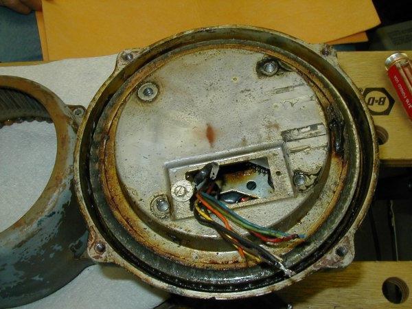
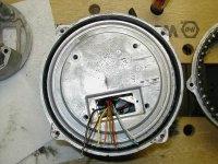
After
removing the old connector and the BRAKE wedge mechanism, we're
left with the wires coming from the motor and direction indicator
resistor.
|
|
|
|
|
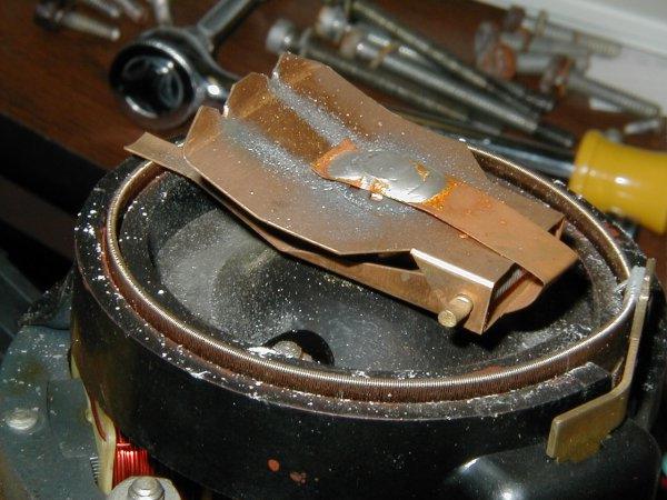
This
close-up clearly shows the top of the resistor which fits into
the top bell housing.
|
|
|
|
|
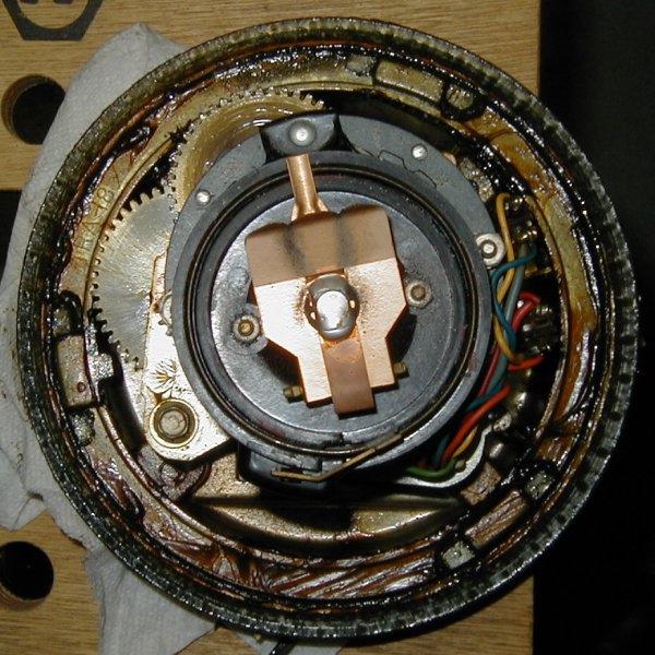
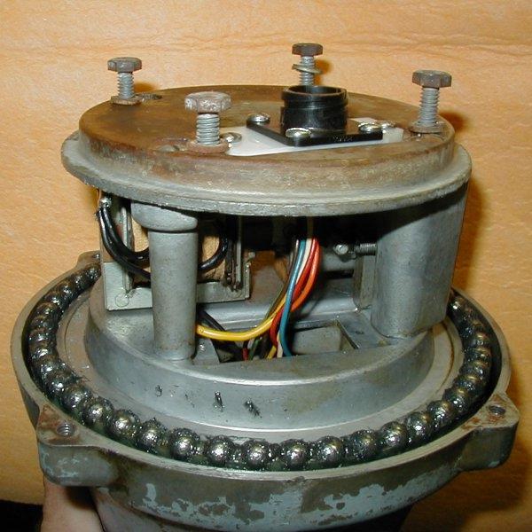
Here's
the direction indicator resistor sitting on top of the motor.
The copper wiper locks into a locator slot inside the top bell
housing. The reduction gears turn a ring gear seen just inside
the outer edge of the rotator in this view. It has 3 large lugs
which fit into slots inside the top bell housing which does the
actual turning. One of the lugs has a tab pointing inwards (seen
next to the gear on the left side in this picture) which toggles
the limit switch when it reaches the extremes of rotation. The
proper way to reassemble the rotator is to connect the control
box to the rotator as you see it here. Turn the rotator to the
full South position in the Westerly direction. This will turn
the gear until the tab pushes against the limit switch and stops
the rotation. At this point, disconnect the control box, turn
the position indicator potentiometer on the top to the full Counter
Clock Wise (CCW) position. Then position the top bell housing
upside down in an appropriate clamping device like this work table.
Position the bearings in their race inside the top bell housing.
Invert the motor assembly and carefully, WITHOUT moving the potentiometer,
position the motor assembly over the top bell housing and align
it so the serrated edge tab on the potentiometer will ingage the
rectangular pot in the top of the bell housing. At this point,
the lugs will align with the three slots in the bell housing and
you can just carefully lower the motor assembly into the bell
housing.
|
|
|
|
|
This
is the same picture you saw before but after all the cleanup and
reassembly of the top bell housing. Mount the bottom/brake assembly
to the motor assembly and wire the connector per the instructions.
|
|
|
|
|
Here's
a close-up of the underside of the new connector with the wires
all connected. You can also see where the large black wire and
the small black wire are connected to a ground lug mounted under
a screw which holds the brake solenoid.
|
|
|
|
|
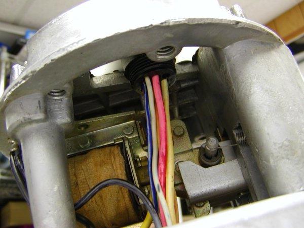
The
new connector is mounted in the BRAKE housing. At this time you
can connect the control box and verify that when the rotator is
turned, the meter moves smoothly to both extremes. When you are
satisfied with this, it's time to put the lower bell housing back
on. Place the bearing assembly in the race as shown above
|
|
|
|
|
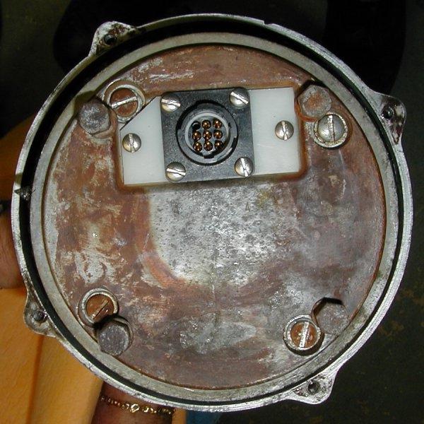
The
connector is all mounted. The rust color on the bottom of this
rotor is from an old steel mast which was used in the past and
discolored the base. We're ready to put the lower bell housing
in place.
|
|
|
|
|
This
a view of the connector installation in a TailTwister (T2X) Rotator
done 10/22/2002
|
|
|
|
|
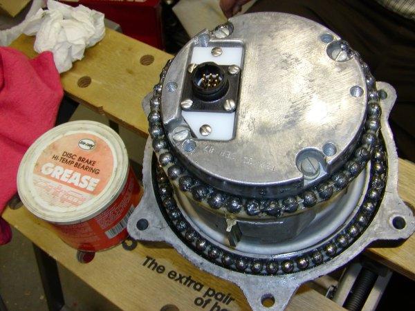
The
T2X rotator has additional bearings at the bottom of the lower
bell housing. Here you can see the bearings and the new connector.
I used high temp disk brake grease for the bearings. The advantage
of this grease is that it is very sticky, doesn't harden and doesn't
flow.
|
|
|
|
|
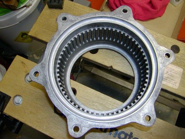
Here
you see the lower bell housing of the T2X rotator. Note the heavy
mounting ears on the outside, the heavy slots for the brake inside,
and the races for both the lower and middle bearing sets.
|
|
|