Author: azkoza@yahoo.com - KB7QPK.MODIFICATION.NET
*Note: The interface described here has been verified to work on the TH-G71 and also the the TH-F6A/TH-F7E.
Background
I wanted to make my own cable to program my Kenwood TH-G71A ham radio with a PC, but the owner's manual simply did not show the pinout needed for the connector plugs. I searched the web but was not able to find this information but I did discover that several other radios used an RS-232-to-logic (0-3.3V) level-shifter and a Full-duplex serial connection (separate RXD / TXD), and found schematics for such interfaces for other radios. I also found a device called the "MAK interface" which claimed to work with the TH-G71A, and the web site listed an interface cable.
With these clues, and after studing the signals coming out of the radio (and lots of debug time ...), I finally figured out the plug connections at the radio end.
I was able to use basically the same interface schematic that was claimed to work for the Kenwood PG-4S cable (which is used for the TM-G707 / TM-V7 radios instead of the Kenwood TH-G71).
Refer to http://www.fiberpipe.net/~tateb/pg4s.html for the schematic for the PG-4S interface:
The DB-9 connector to the PC is the same, but the connector on radio side is different. (Instead of the 6-pin mini-DIN connector, use the 2.5mm and 3.5mm phono plugs for the TH-G71)
Refer to Drawing at the URL above (Tate Belden's site), right hand side, starting at the top:
- Ignore the tie between pins 4 and 5 of the mini-DIN connector. (There is no such tie on the TH-G71 Cable)
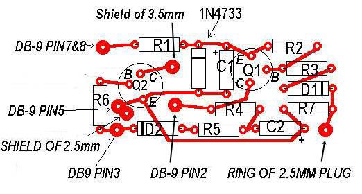
- The interface's "TXD" goes to Ring of 2.5mm plug. (cathode of the diode on the interface)
- The interface's "RxD" goes to the Shield of 3.5mm plug. (collector of NPN on interface) (Or just use a mono 1/8" jack and connect this to the shield!)
- GND goes to shield of the 2.5mm plug.
- The tips of both plugs are No-connect.
Schematic tweaks:
Note: If you have an interface that already works on another radio such as the Kenwood TM-G707 / TM-V7, then you may not need to make these changes!
- Change R1 from 150ohm to 1K ohm (this is the resistor feeding the zener diode). I found that 150ohms loaded the line too much and the resulting voltage was too low to power the interface from the Serial port. If you have problems, be sure that the cathode of the Zener is at about 4.9V. I found that the interface worked down to about 3.2V when I just powered this from a variable power supply instead of through the PC serial port (after removing R1 and the zener and just applying voltage at C1)
- add a 150K ohm resistor between the Radio TXD to gnd. I did this just to keep the voltage down on the TxD pin because the radio seems to be 3.3V I/O pin (not 5V)
TH-G71 PC cable interface plugs.
                _________  shield  ring  tip

               |         |_______ __ __

   2.5mm plug  |         |       |  |

   (3/32")     |         |_______|__|__/

               |         |  |     |   |_ N/C

                ---------   |     |

                           GND   Radio TXD (out)


                _________  shield  ring  tip

               |         |_______ __ __

   3.5mm plug  |         |       |  |

               |         |       |  |   |---- N/C

   (1/8")      |         |_______|__|__/

               |         |   |     |_________ N/C

                ---------    |

                             |________ Radio RxD (in)
Update: Dec 2001: The Kenwood manual for the newer TH-F6 radio shows the pinout for the Plugs (page 46). Through Dec 17, 2001, this web page showed the Ring and Shield of the 3.5mm plug both shorted together, but I have updated the plug pinout to match the Kenwood documentation, and I confirmed that it does work as shown, without the connection to the ring.
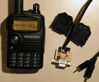
I was able to find a 90-degree "elbow" shaped, 2.5mm stereo plug at Radio Shack (p/n 274-298).
Here is the resulting schematic:
Disclaimer: Although this works fine for me, use at your own risk.
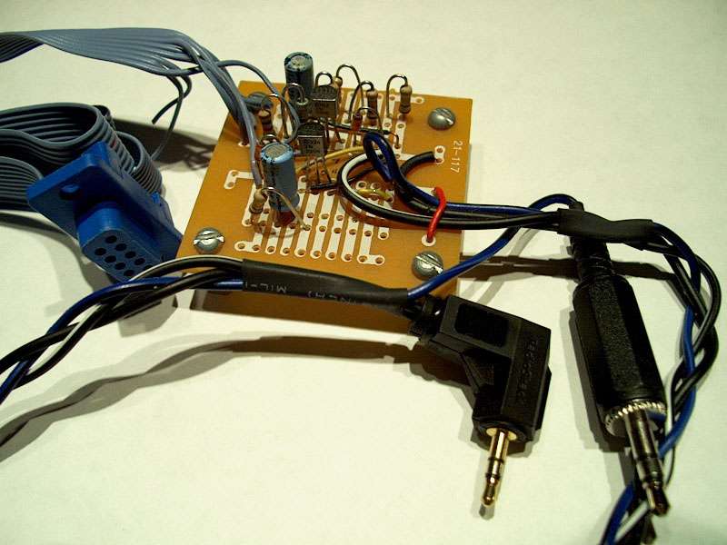
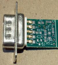
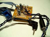
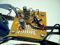
Building it - my homemade interface
I built the interface on a Small PC board originally purchased from Circuit Specialists , Mesa, AZ.
It is "Datak" brand prototyping board part number 12-607.
(RadioShack.com carried them as p/n 910-3811 (in their catalog) but I don't see them on-line anymore.)
A recent Google Search on datak 12-607 found the following as possible sources:
Click a figure to pop up a larger view of that figure in a new window.
 |
 |
 |
| Interface Photo 1 |
Interface Photo 2 |
Component Placement Diagram |
Other implementations
Using the interface / software
- For TH-G71: Menu 15, TC ON
Tranceiver Control must be enabled, or else you will get a communication timeout error when trying to communicate with the radio after connecting the cable up to your PC. "TC ON" enables the plugs on the side to work as data lines instead of as external mic/speaker.
      Press the "F" button, and then Band, turn the main tuning

      knob to Menu 15 Transceiver Control and turn it ON for

      programming.  You will need to use a free com port (Com 1 or 2) on the PC.
Note: For the TH-F6 radio, the Kenwood manual states: Access Menu No. 9 and select "PC"
- Kenwood Programming software
Download the PC Programming s/w from Kenwood FTP site ftp://ftp.kenwood.net or web page http://www.kenwood.net/amateur -> downloads -> software -> THG71A
You should see the files mg71200.exe and readme.txt.
Install the software and Run mcp-g71.exe. go to file menu, and be sure your com port is set correctly, then turn on radio, and plug in, and do "Radio-> Read". Try it a few times -- I found that it sometimes said something like "Communication timeout" the first time I tried after connecting up the interface.
Debugging problems with the interface
- Be sure you have done everything listed under "Use". If you are really stuck, you can try these checks:
- Verify power + side:
- With the interface connected to the pc, connect a meter to node 1 (cathode of the Zener) and ground.
- In the MCP program, do radio->read (you should see "reading data from radio") As it is "trying" to read the radio, quickly check the voltage.
- The voltage should be about 4-5 Volts. This is needed to power the interface from the serial port.
Note: The voltage at the RTS and CTS pins of the DB-9 connector will NEGATIVE when the Com port is inactive (when you are not trying to read or write to the radio with the software). But the voltage will go POSITIVE (about 9V on my PC) when the Com port is active.
| Condition |
RTS/CTS Voltage |
| Com port idle, not reading/writing radio |
about -6 to -12V |
| Com port active, reading/writing radio |
about +6 to +12V |
- If you don't have good power here, something is wrong. (This is why I increased R1 resistance from the original schematic - as the original lower value loaded my serial port down too much due to the diode at node 1).
You can power the interface externally:
Remove the rts/cts connections from the PC and just power node 1 with a battery or external power supply. This was the main problem I had getting my interface working (besides trying to figure out the pinouts of kenwood jacks).
- Verify power negative (-) side:
- With the interface connected to the pc, connect a meter to node 7 (negative terminal of the Cap C2)
- In the MCP program, do radio->read (you should see "reading data from radio" As it is "trying" to read the radio, quickly check the voltage.
- The voltage should be negative (more negative than about -5 or -6V) This is needed to generate a negative voltage back to the PC RxD.
- If this power is good in the previous steps, but the interface still does not work, recheck the interface to make sure everything is wired up correctly including all ground connections, and the pinouts the serial port DB connector. Check all part values and that the polarity of caps is correct, and that NPN and PNP transistor are wired up the correct way.
- If that does not find any problems, I would then test the interface to be sure it does the correct level-shifting and "inversion" of the levels from the PC (RS-232) to lower-voltage for the Radio.
This can be a bit tricky and you need some power supplies and clips todo this, with the interface disconnected from the PC and the Radio.
Basically, you want to verify the following:
- With TXD (out from the radio) = 0V, the RxD to PC should be about 5V
- With TXD (out from the radio) = 3-5V, the RxD to PC should be between -5V to -12V.
- With TXD (out from the PC) between -5V to -12V, the RxD to the Radio should be "floating" (Q2 off) (and the weak pullup in radio pulls the node to a logic "high" value)
- With TXD (out of the PC) > 5V or so, the RxD to Radio should be 0V (Q2 is "on").
But the catch is that the interface generates the -12V (or so) by the switching on TXD. So you need to fake it out to be sure you have this voltage (which should be there in step 3c) because you don't have the interface connected to the PC anymore. Otherwise, you won't get the negative voltage in step 5B.
Programming the TH-G71
See this
page for information used to program and control the TH-G71
through a serial port. Serial Port command protocol is provided.
This is useful if you are interested in how Kenwood's MCP memory
control program works, or if you are interested in programming the
radio using a PC.
Chris Koza KB7QPK
|