Copper Plumbing Pipe Dipole Antenna for 2 Meters
by W4ZT

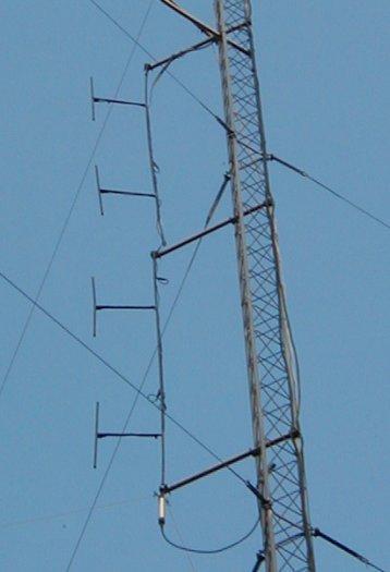
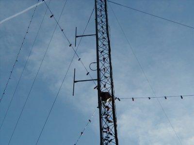
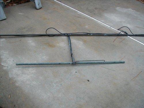
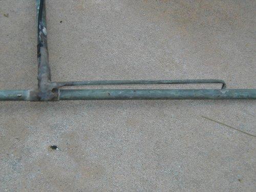
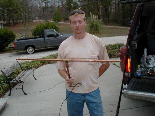
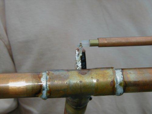
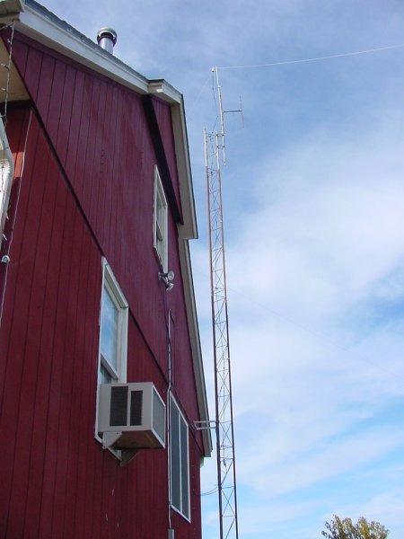
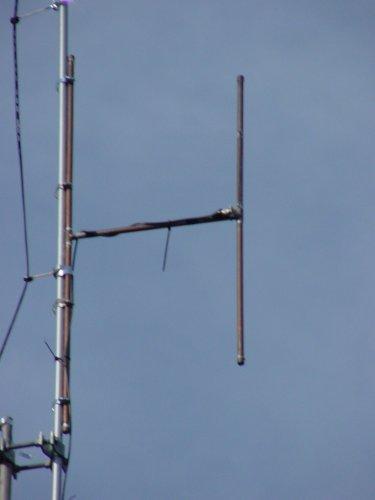
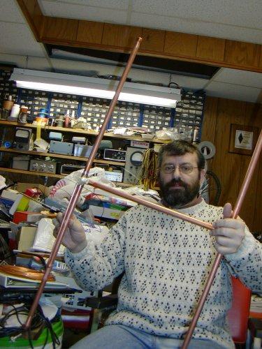
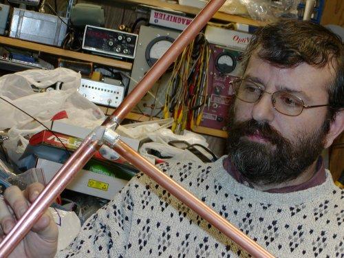
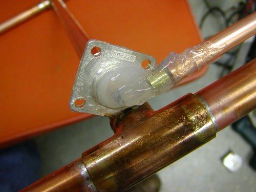
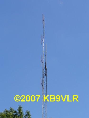
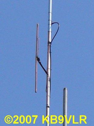
During the late 1980's I worked up the design for these dipoles during a vacation week at home. I was looking for an antenna design for a repeater antenna. The design I wanted was something that was grounded to help prevent static buildup problems, was easy to build and could be duplicated over and over without redesign. These dipoles are the result of that effort and do a good job.

One of these dipoles works fine for a basic, slightly off center, omni-directional antenna. The angle of radiation is lower than that of a ground plane so it does tend to work better (by about 3db in the favored direction). You can use more than one by stacking them vertically and feeding them in phase. Each time you double the number of dipoles you increase the gain in the favored direction by about 3 db but the amount of work that goes into the phasing harness and the losses might make it undesirable to stack more than 2 or 4. Stacking distance is just under 39 inches tip to tip so a pair of dipoles will be about 12 feet long. I built 8 dipoles and did put all 8 up in phase. They worked great but were VERY long and the phasing harness was a bear to build and install. If you want to go that far I might be able to give you hints but you're on your own after that. ;-)

If you build one of these antennas I'd love to hear from you and see pictures of your work.

73, Tony - W4ZT

(Click on the small pictures to view a larger picture in a new browser window.)
Currently, 6 of the 8 copper pipe dipoles I built, are on the tower. These 4 near the top (top of the dipoles is at about 95 feet) are fed in phase (using a home made coax phasing harness). The feedline goes to the lab.
 
The other two are much lower (at about 35 feet), also fed in phase, and are connected to the 2 meter radio in the dining room.
 
This is one of the old dipoles laying on the ground. You can see the nice patina of the copper on the old dipoles.
 
The gamma match is a piece of 1/4 inch copper tubing which is soldered into a hole drilled in the appropriate place along the 1/2 inch pipe.
 
The connection between the gamma match and the connector (I used BNC but use what you like. See the other pictures showing the use of a UHF SO239 connector below. Note that the silicone sealant keeps moisture out of the connections.
 
These drawings may help you understand the construction. They are not to scale and the gamma match is offset to provide better detail. These dimensions worked for me. You should make sure ONE dipole works properly for you before you build more. In mine, each side of the dipole was made using an 18 7/32 inch piece of pipe and the support arm was a 17 inch piece of pipe. That worked out for the fittings I had. You will need to double check yours before soldering.
 

The chassis mount BNC connector is soldered into a "U" shaped piece of copper wire which is soldered into holes drilled into the copper pipe. The SO239 connector works well in this application as the photos below show. See the detailed photos and note the slot which the corner of the connector is soldered into.

The gamma match is 1/4 inch copper tubing. At the end near the connector, a piece of RG59 coax center conductor is slipped inside a piece of brass tubing which telescopes into the 1/4 inch copper tube. It is then soldered to the connector. Sliding the brass tube in and out over the small exposed piece of the coax center tunes the gamma match. Note that the RG-59 center is just used as the gamma match. Feed the dipole with 50 ohm coax unless you are building a phasing harness for multiple dipoles (detail of the harness is not given here but it is a common "odd quarter wave" matching harness).

 
The gamma section inside detail: New and Old.

The center is a piece of RG59 coax center conductor cut to 4 1/8". Strip 3/8" of the insulation away and make a right angle bend. NOTE: The insulation will come right to the bend. The insulation has come away from the end of the old wire during disassembly.
The center conductor is telescoped inside of a 1 1/2" length of 3/16" brass tubing which will telescope inside the 1/4" inch tubing of the gamma.
 
The SO239 connector makes a good choice for the dipole. I cut a slot in the "T" connector as seen above with a die grinder and cutting wheel. The slot is sized so that the corner of the connector will fit snugly into it.
 
The SO239 fits just right in a slot cut with a cutting wheel on a die grinder.
 
The connector ready for soldering.
 
You can see the slot here with the connector in place.
 
The connector and gamma match are assembled and the antenna is ready for adjustment.
 
Another view of the connector and gamma adjustment.

Henry - KM4O/W4HK (SK)
Holding his new dipole.

This is Van - KF4LEX
Holding a brand new dipole that he built.
Closeup of the feed point on Van's antenna before the connector.
Another closeup of the feed point on Van's antenna. He hadn't mounted a connector at this point but had connected the feedline to do preliminary adjustments. Nice job Van!

These three photos come from Bill Kuhn KC0NYL in Saint Marys, KS who found this web page and decided to build the dipole. As a new ham he was looking for something easy to build and that would work. I've enclosed his email below so you can see his comments.

"Subject: Plumbers' Dipole Antenna
Date: Fri, 13 Sep 2002 13:39:21 -0500

I just wanted to drop you a note and thank you for the plans for the dipole antenna. I am a brand new ham and your dipole has become my first fixed antenna. It works great!

It is temporarily mounted at 19ft on 2 sections of Rohn 15G tower that is bracketed to my garage. I picked up 60feet of used and mildly corroded (but still solid) 15g and am currently in process of sanding and painting before I dig a hole and mount it permanently.

Next step for me is a 10 meter antenna - I haven't decided what to build yet. I have a 10 meter wire dipole up now connected to a Radio Shack HTX100 so I can listen to 10 meter CW in preparation for my code and General exams in October. Eventually I'll cough up the $$ for a good HF rig.

Many thanks! That was a nice easy project and the directions were great!"

and followed up with this:

"Subject: RE: Plumbers' Dipole Antenna
Date: Sat, 9 Nov 2002 15:17:19 -0600

Sorry I'm so late getting pictures back to you - I waited until I finally got the antenna up on 50 feet of tower (today!) and took some shots.

It is underneath a G5RV which is my only other antenna on the tower for the moment. I passed code and General theory in October so I bought a Kenwood TS-530S so I can play on HF for the winter. I'm going to take a crack at the Extra exam in December.

The most astounding thing about the Plumbers' Dipole is that I built it according to what is on your site, mounted it, and started using it. I didn't have an SWR meter to check it, so I never tried to tune it. When I finally got an SWR meter, it shows 1.1 to 1 on 146.955 (my primary repeater), and doesn't hit 1.3 to 1 on either end of the band!! When I took it down to mount it on my main tower, I just made sure it was sealed reasonably well and up it went. No change in SWR. I'm absolutely thrilled!

73's
Bill Kuhn
KC0NYL"

Nicely done Bill and congratulations!


This is Gordon, N4LR, holding his new dipole - 12/14/2002
Details of the connector and gamma match seal

Subject: copper dipole
Date: Sun, 13 Mar 2005 10:46:35 -0500
From: Warren (VE3FYN)


To: W4ZT

Hi Tony,

I built your copper dipole. It's a good antenna. VSWR measures under 1.5 between 136 and 154 mhz. Reception and transmission are comparable to similar commercial antennas I've used.

I modified the gamma match a little by using a 5/16 tube with a 3/16 tube on the inside.

73
VE3FYN, war

Warren Paulson VE3FYN
Reply to:
QTH: Atikokan, Ontario
Grid: EN48ES
*****


Subject: RE: copper dipole
Date: Sun, 13 Mar 2005 11:07:45 -0500
From: Warren (VE3FYN)
Reply-To:
To: W4ZT

Tony,

Yes, I did the mod because I didn't have access to the brass you suggested. I did have to grind down the inner tube somewhat to make it slide easily. It's a good fit only if the tubes are dead straight -- since they're flexible, they usually aren't. I also made the inner tube somewhat longer than you had spec'd for the brass tube, simply so the antenna cable wouldn't be flopping around in the larger outer tube.

I'm mounting it on my roof today to serve as the antenna for my APRS I-Gate.

Cheers,
VE3FYN


4 Dipole Array Built by Adam KB9VLR - 9/2007
-------- Original Message --------
Subject: 2 meter dipole antennas
Date: Mon, 10 Sep 2007 12:45:54 -0500
From: Bain Adam
To: Tony W4ZT

Tony,

I built a phased array using four of your dipoles. The build was simple and fast, and the performance is very good so far. I shortened the dipoles by about 1/4" on each leg, and left the gamma match the same. This helped the SWR out a bit on the MURS band (151 and 154 MHz), since I go up there to chat with some non ham friends.

I used a MFJ 259B analyzer to test and tune each dipole, then used it to trim each 1/4 wave phasing cable. Each dipole performed under 1.5:1 SWR from 142 to 158 MHz. I used RG59 cable for the dipole to Tee connectors, then LMR400-75 for the TEE to TEE phasing.

After mounting the array to the side of the tower, performance is still very good. 1.5:1 from about 140 MHz to 156 MHz with a 75' run of LMR400 up the tower. All SWR measurments were using the 259B analyzer.

Signal report is very good. The distant repeaters I could just barely hear are rock solid now, and it's got very good performance with portable units. I've attached some pictures of the install, for you to check out. One thing extra I'm trying, is I've coated the copper with a clear enamel paint from a local home improvement store. It's marketed to prevent corrosion in exposed metals (we'll put that claim to the test!). The SO-239 and connecters were coated with silicone sealer for mechanical and weather protection, as mention in your construction plans.

Thanks so much for the plans, and for your website!

73's KB9VLR Adam

Links to other antenna projects of interest:


Last update was on September 11, 2007 9:30