Power
Supply Dummy Load
Using the switches the current can be varied from a single bulb to all 12 bulbs on either load which essentially means there are two load banks, one with a load range of about 600 ma to 7.5 amps and another with a load range of approximately 2.1 to 25 amps. The two could be combined externally to provide a maximum load of 32.5 amps.
This isn't a construction article, just a show and tell to give you some idea of what can be done for cheap. I had the scrap of circuit board and the slide switches were salvaged from an old piece of junk. The only thing purchased was the bulbs at about $1 each, the Power Pole connectors at about $1 each, two short lengths of red/black wire, and four carriage bolts with nuts and washers.
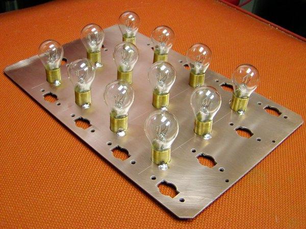 |
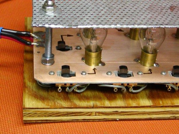
The bulbs are mounted in holes drilled into a piece of single sided printed circuit board. The holes are sized to be snug and then the brass base is soldered in place. |
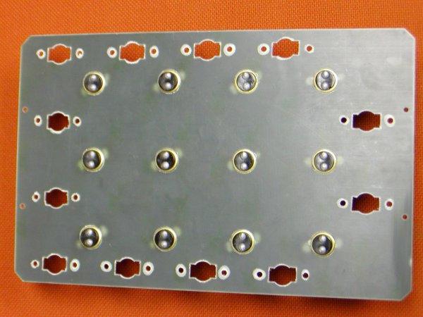 |
On the bottom of the board the filament connections are seen. These are wired to the switches. |
|
|
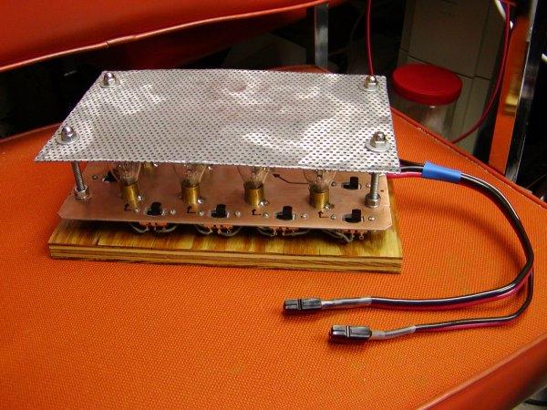
The perforated plate was placed on top to protect the bulbs from physical damage. Glass breaks and this load will get bumped around. |
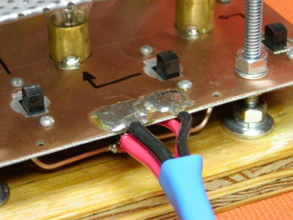 |
Business end of the load bank. The black wires are soldered to the top side of the circuit board making contact with the bulb bases. The red wires are soldered to pieces of #12 wire that I ran from end to end between the switches. Then each of the other switches were wired to the #12 wires with short lengths of #18 insulated wire. |
 |
You can see the bulbs and switches in this view. They are spread around the perimeter of the board so they can be switched without interference from the top perforated cover. |
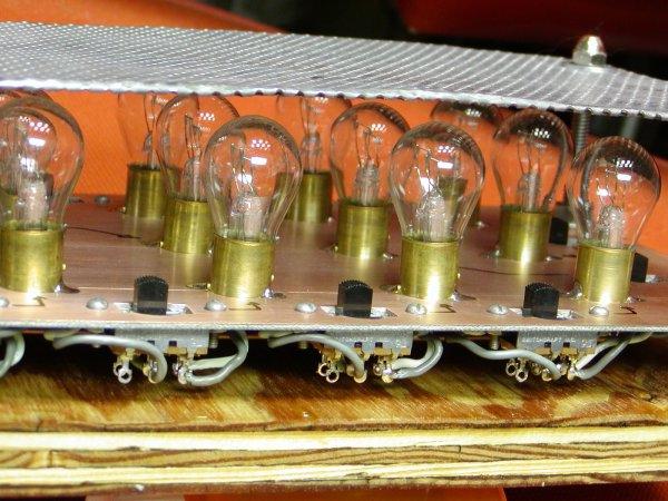 |
Close-up of the bulbs and switches. |